05/01/23 - Painting Tool Progress

Current Mechanic State
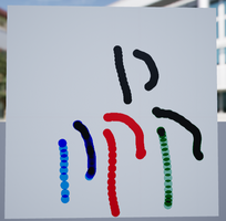
I have currently completed the drawing tool to a base state that I am happy with. The player is able to draw on a whiteboard surface with four different colours and can erase the canvas. A video showing the tool in action is shown in the link below.
https://drive.google.com/file/d/1Sma5Bq5BILgCl74sr-tby991x1PgSGRa/view?usp=share...
This does have some issues however, while the snap turn issue you can see when selecting the pen is a radial tool issue, the method I used to achieve this does have setbacks. One of these is that way that the position of the pen is mapped to the position of the whiteboard canvas. This is shown below.
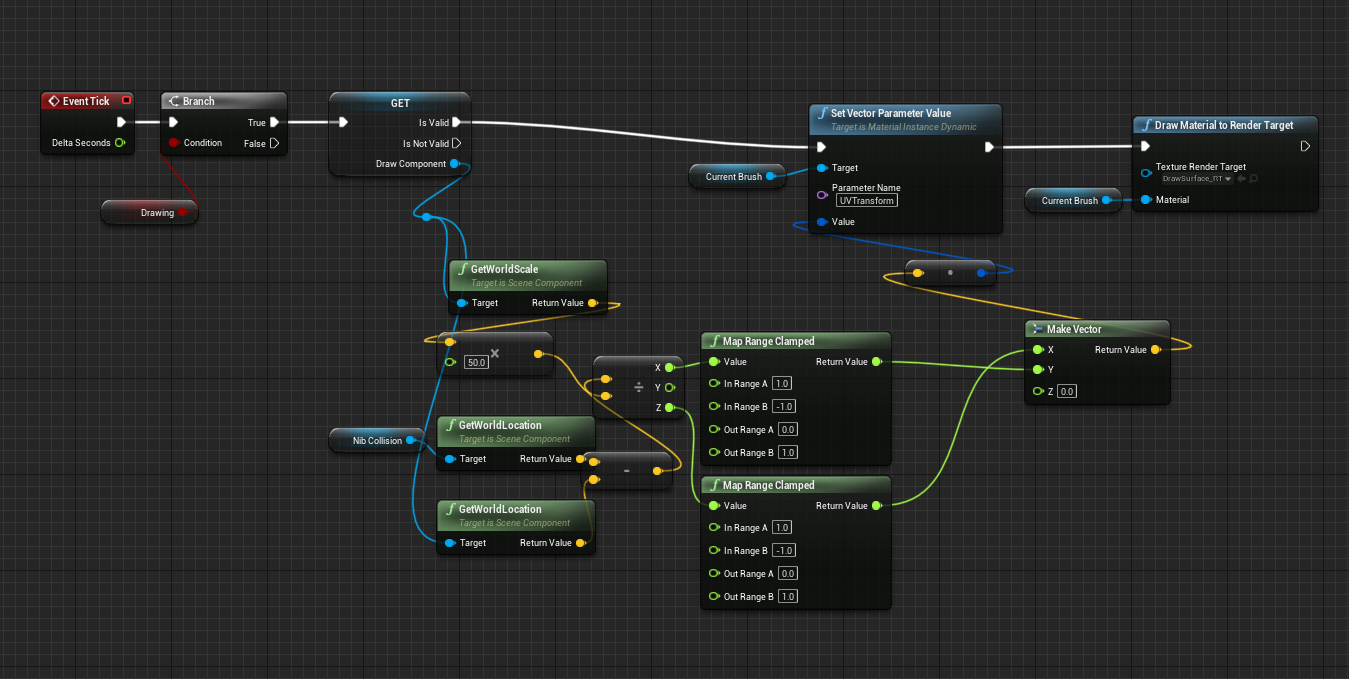
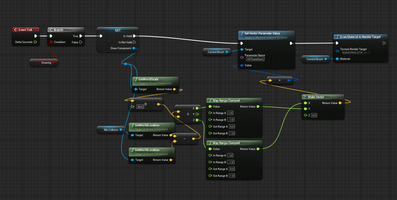
For the draw tool to work, the position of the pen has to be mapped to a 0 - 1 range relative to the whiteboard so the render target can be drawn onto at those exact coordinates. Currently this code is designed with only the current whiteboard in the scene in mind. It completely ignores the Y coordinate of the pen as the whiteboard is just a plane and does not require depth. If the whiteboard were to be rotated a few degrees, it would completely break the code. To fix this, the world coordinates of the pen nib need to be translated into the local coordinates of the target whiteboard. This would also allow it to be functional at angles that aren't strictly locked to the worlds x and y.
Another issue is to do with how the render target I used processes colour, it does not allow the player to overlap colours, the result is always black. This is shown in the video in the link below where I initially discovered the issue. I currently do not know how to fix this as I am not knowledgeable on how RGB channels work and how this could be avoided.
https://drive.google.com/file/d/1kEVrtCOWWy0SFYRj2KVyZlvlByKqZth8/view?usp=share..
Development process
Pen design
For the drawing tool, I wanted to create a simple pen that the player could use with four colours, much like the popular 4 colour pens made by BIC. I wanted the player to be able to cycle through the colours with two buttons for forward and back and the pen would change to reflect that. This was also a good way to ease myself into the process as I felt the actual drawing code development would be quite difficult.
The pen consists of seven components, the base, four colour notches, the nib, and a collision capsule for the tip as shown below.
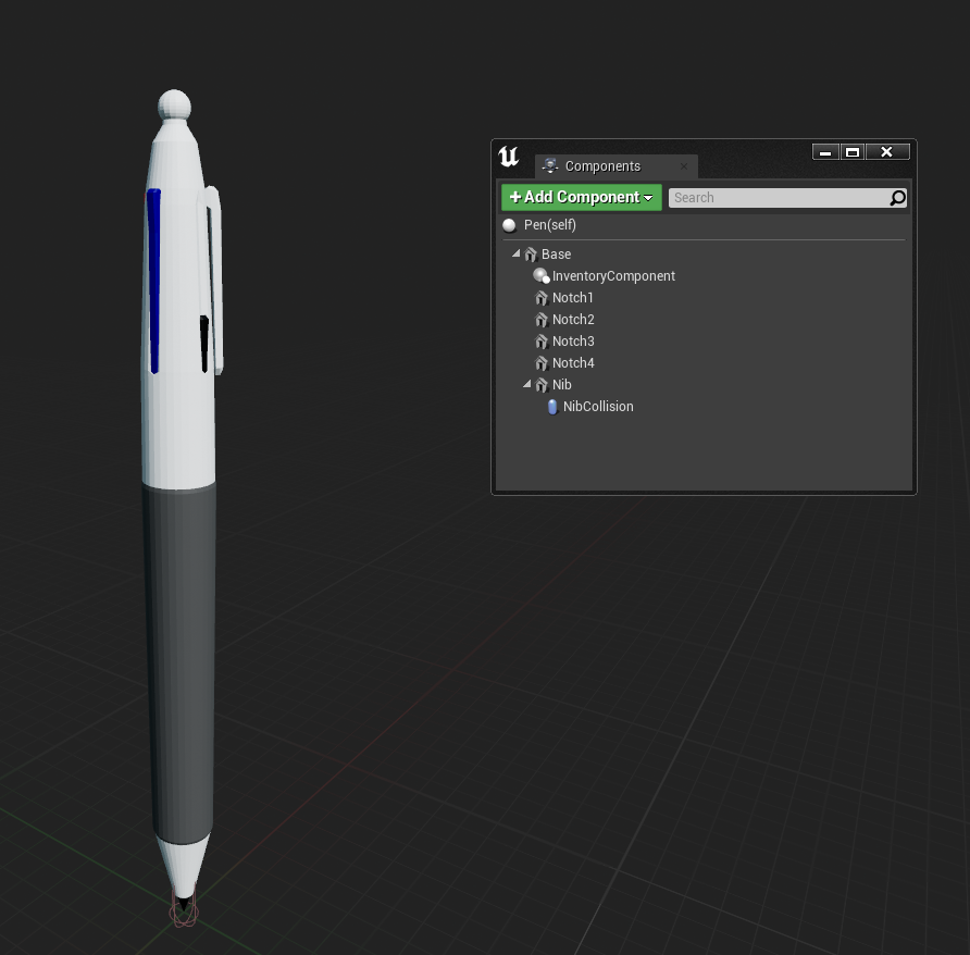
The collision capsule extends further in front of and behind the pen's nib, this allows the player to not have to align the pen perfectly with the board which would be difficult to maintain.
Colour selection
To increment/decrement the pen selection the VR BPI interface buttons I added were used this is designed to work with either hands buttons but I have not yet implemented a switch dominant hand option which would hake use of this (this will likely be added in the in-game diegetic menu). The code uses the upper button (B/Y) to increment, and the lower button (A/X) to decrement the selection as shown in the second highlighted comment section.

Pen Rotation
The pen is then rotated to make the selected colour notch face the player. This was unexpectedly difficult. Initially the above option of rotating the inventory component (Grab component I created for inventory items) did not work and I had the issue of rotating the base where it would rotate around the origin of the pen (the Nib) at an incorrect angle causing the pen to be held completely wrong. As it turns out, rotating the inventory component did work, but the visual change did not commit until the player would detach and re-attach the inventory component to the players hand by selecting another held item then going back. This was circumvented by adding a new function in VR Pawn dedicated to just re-attaching the pen for each angle change. Unfortunately this means that this rotation of the pen cannot be animated and can only snap the the new rotation.
Animation
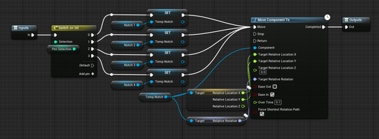
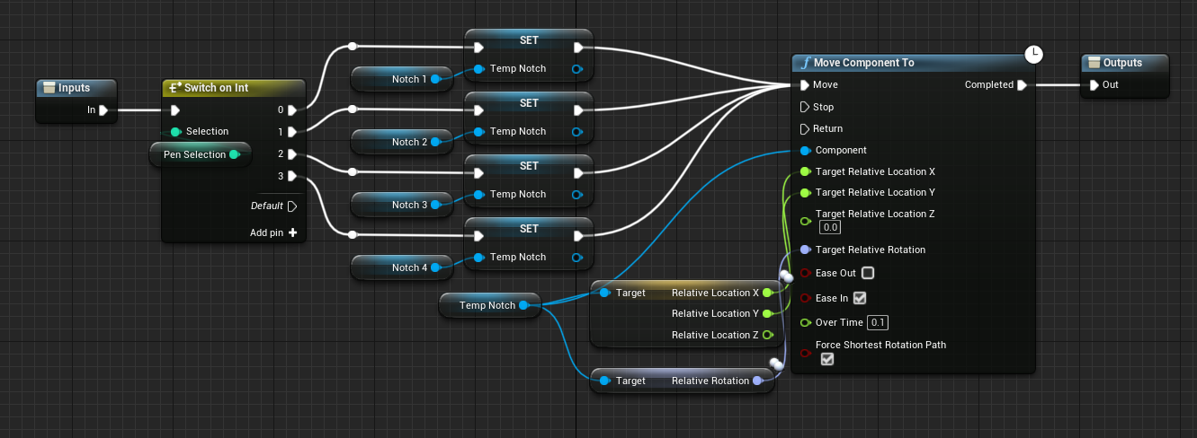
To add some detail to the pen, I decided to animate the colour notches being pushed down and returning once another is selected, these are the "Anim" macros in the above section showing all of the colour selection process. The notch is selected based on the pen selection integer then animation to the up or down position using move component to. The below image is the up animation. The down animation is the same aside from the relative z being set to -300 and ease out selected instead of ease in. The up animation is placed before the pen selection change so I don't have to create another variable storing the last selected notch.
Setting Colour
After all the above, the colour of the pen is set. There is a visual colour change of the pen nib material then the "Current brush" variable is set, this is what actually changes the colour output of the brush and will be explained further below when I get to the actual drawing mechanic.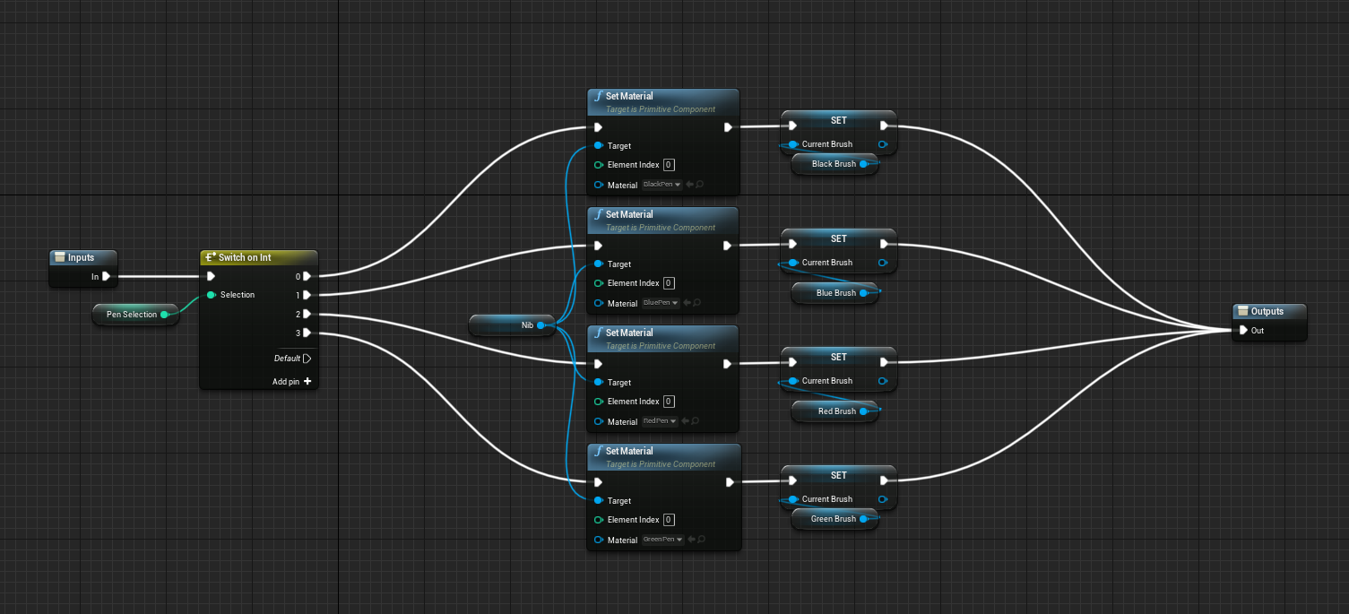
Drawing Code
The general process of the drawing mechanic stems from this tutorial I found which is designed to teach how to draw bullet damage to objects.
This tutorial taught me the feature I needed to know - Render Targets. And the follow up video "Drawing Damage directly under the crosshair" helped me to apply the render drawing brush to the direct coordinates of the pen.
Triggering the drawing state
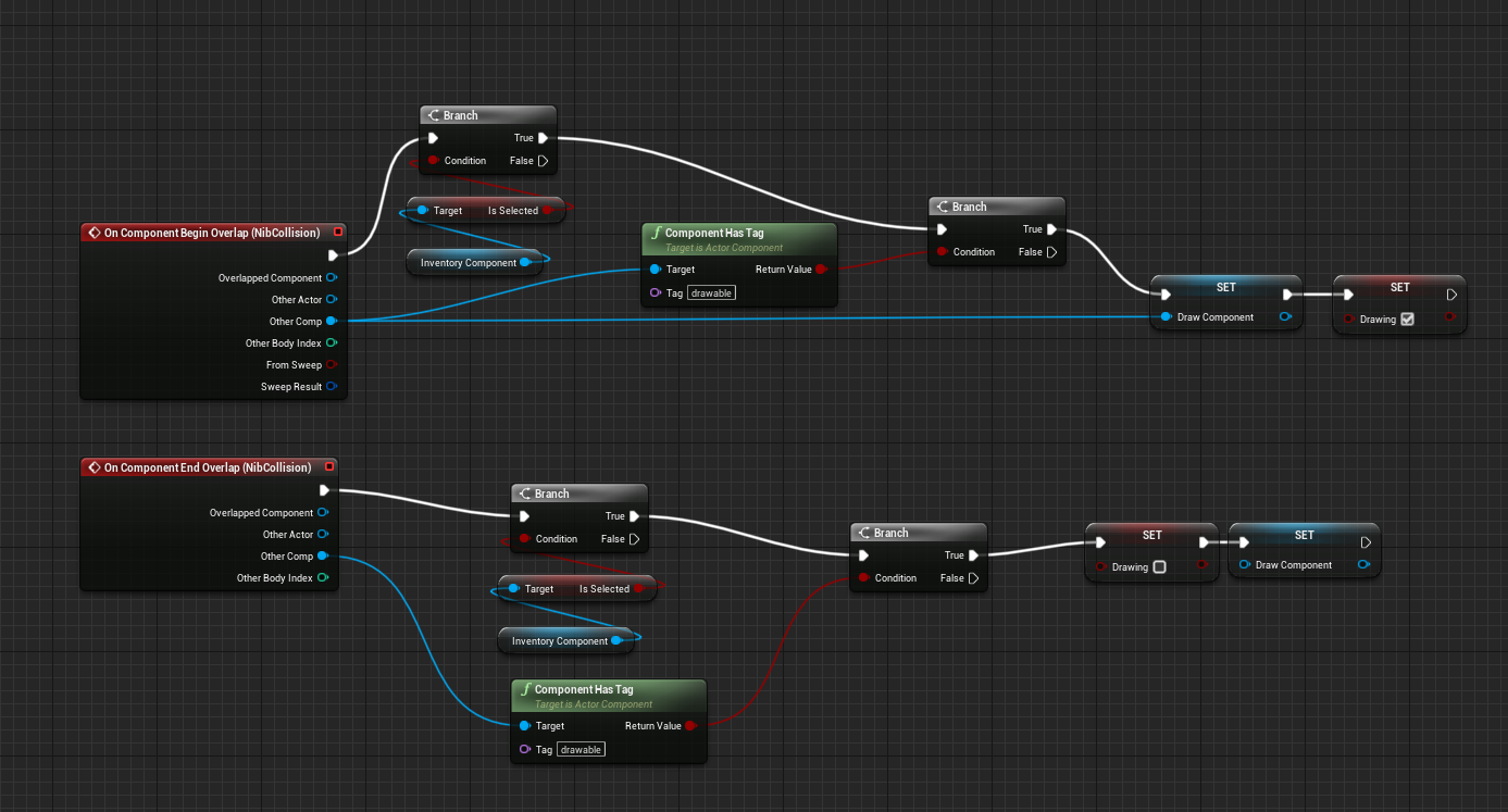
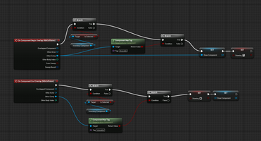
As I planned to draw to the render target using the event tick node I had to have a method of setting when I should and shouldn't draw. For this I created a Boolean variable called Drawing. There are two branch checks before setting this variable, one checks whether the pen is selected using the inventory component attached to it. The second checks whether the collided object has a specific tag "drawable" this is so that the drawing isn't triggered on every collision. It also allows to draw component to only be set to a drawable object. The draw component itself is vital as it is the plane that the render target is attached to, allowing us to get the relevant coordinates.
Setting up brushes/materials
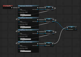
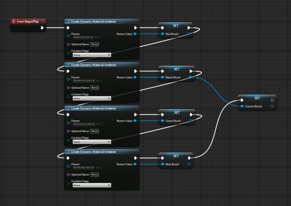
When the game starts, four dynamic materials are created, making the material dynamic allows variables within the material to be changed, this is necessary for setting the draw coordinates. The initial "current brush" is set to black to start. This current brush is changed in the "setting colour" section shown further above.
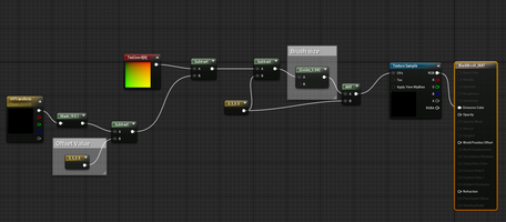
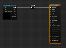
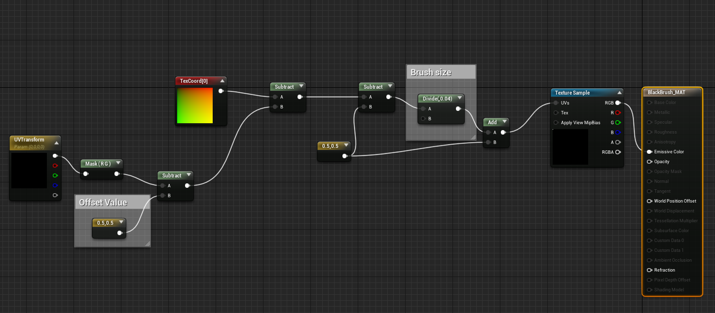
The setup for the materials was taken from the above mentioned video "Drawing Damage directly under the crosshair" The offset value moves the texture to the top left which is then moved by the UVtransform vector. This is the variable that is changed from the blueprint. The divide node changes the size of the brush material. The actual brush itself is just a coloured circle depending on the brush colour.
Mapping code
By creating the dynamic materials mentioned earlier, the set vector parameter value node becomes available. This is how we set the positioning of the brush dot; instead of the brush material being taken as a whole and added to the render target at a specific size/coordinate, the changes have to be done in the brush material itself with it then being added to the render target at 1:1 scale and position.
This below code is overly complicated and does not take into account canvases that could be places at different angles, but for now it works. The vector value put into the UVTransform material node has to be in the scale 0 - 1 for both x and y where 0,0 is the top left.
Currently, the code gets the position of the pen nib on collision and subtracts the centre position of the whiteboard from it. This returns a value giving the pens coordinates relative to the whiteboard. These are then divided by the scale and a factor of 50 to move it down to -1 to 1 with 0,0 being the centre of the board. However the vector coordinates need to be 0 - 1 with 0,0 at the top left so they are remapped with a clamped range mode to avoid any bugs with the values going over. These remapped x and z values are reassembled into a vector as x and y positions and passed into the UVTransform material node.
The could be hugely simplified by using transforming to local coordinates and also allow compatibility with non-strict angles. This will likely be my next step with this mechanic.

Colour Inversion
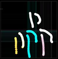
The render target that is drawn to has a black background, I initially intended to mask out the black and add it to a white background texture but not only would this make the black pen redundant without a workaround, it also wasn't possible for me as the alpha channel of the render target appeared to be entirely white, regardless of what was drawn on it. I came up with a workaround, keeping the background black but inverting the pen colours as shown below.

The render target was then inverted for the material using a one minus node.
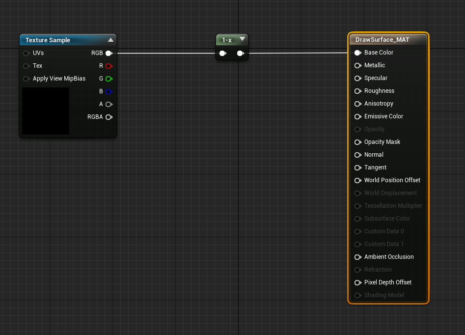
I had some initial issues with the brush colours where some of then were transparent, this caused them to overlap to become white which corresponds to black on the inverted material. There were also the lines appearing which was easily fixed by adding a black border to the brushes.
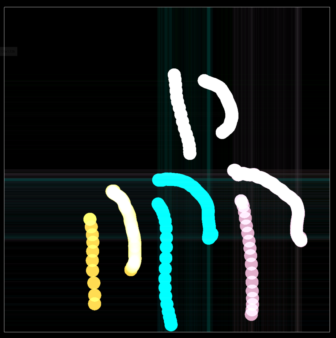
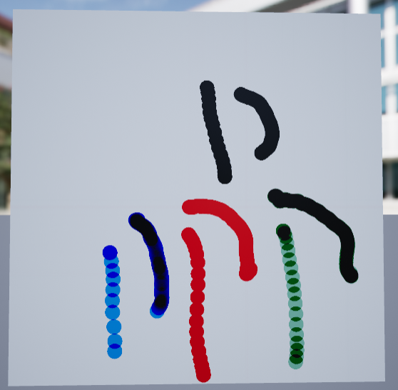
While I initially thought this was due to the saturation or lightness value of the brushes, it turned out to be that only brushes with minimum or maximum RGB values for each channel worked. While this aligned with the red green and blue colours I initially intended to add, it also means I cannot add more colours to expand the tool without finding another method. I could also not customise the green to the darker version I initially had which is shown in the image above.
VR Dev Blog
| Status | In development |
| Author | Georgonzola |
More posts
- 20/01/23 - Button, lever and in-game menu (final state)Jan 20, 2023
- 20/01/23 - Painting tool (final state)Jan 20, 2023
- 20/01/23 - Radial Menu (final state)Jan 20, 2023
- 19/01/23 - Button, Lever & In Game Menu progressJan 19, 2023
- 19/01/23 - World to local coordinate translationJan 19, 2023
- 06/01/2023 - Door ProgressJan 11, 2023
- 06/01/23 - Radial Menu ProgressJan 06, 2023
- 30/12/22 - BreakthroughDec 30, 2022
- 19/11/22 - Current ProgressNov 19, 2022
Leave a comment
Log in with itch.io to leave a comment.